
Size Your Bottom-Drain Air Pump by Depth, Flow, and Real Operating Pressure
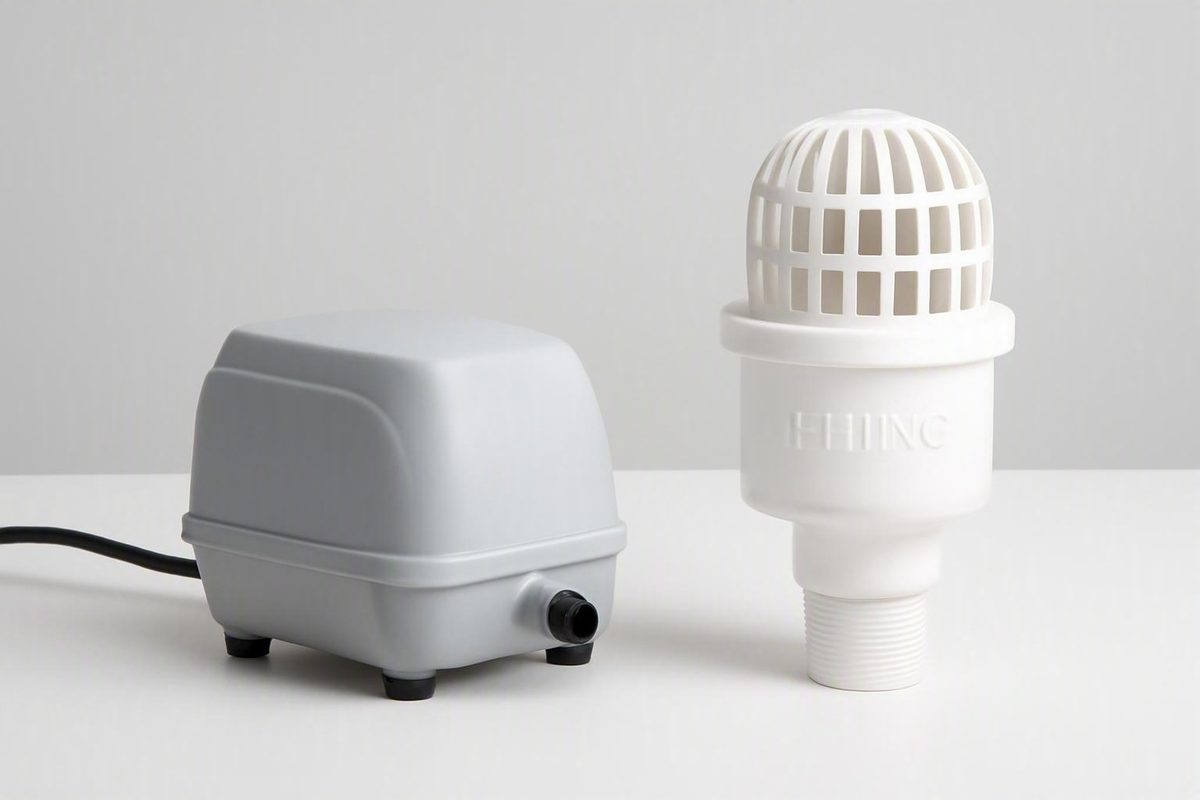
A 40, 60 or 80 L/min label does not prove suitability. Compare delivered output on the pump curve at pressure from the installed drain.
The short answer: start with 1–2 CFM delivered per drain
For one Rhino aerated bottom drain, begin with approximately 1–2 CFM, or about 28–57 liters per minute (L/min), of delivered airflow. “Delivered” means the air reaching the submerged diffuser at the drain’s actual operating depth—not the pump’s unrestricted output at the surface.1
This is general retailer guidance for aerated bottom drains, not an official Aquadyne specification for every Rhino model. The evidence available here does not establish a Rhino diffuser’s recommended flow, maximum flow or pressure loss. Confirm those model-specific details with Aquadyne or an authorized supplier before buying a pump.
Use the range as a preliminary sizing target rather than a universal operating setting. Useful airflow can vary with:
- Vertical water depth above the diffuser
- Diffuser resistance
- Airline length and internal diameter
- Bends, fittings and check valves
- Control valves and manifolds
- The number of outlets running simultaneously
- Pond shape and floor geometry
- The desired amount of surface disturbance
A pump advertised as 40, 60 or 80 L/min is not automatically suitable. That label may describe unrestricted or low-pressure output. Once the pump must push air through plumbing and a diffuser beneath several feet of water, its delivered output may be lower.
The purchasing rule is:
Choose a pump whose pressure-flow curve shows that it can deliver the required airflow per drain at the complete operating pressure of the installed system.
Complete operating pressure includes the pressure created by water depth plus resistance from the diffuser, airline and components. It is not enough to match the pump’s headline L/min figure to the preliminary airflow range.
A compact buying framework looks like this:
| Question | What to establish |
|---|---|
| How much air is required? | Start with 1–2 CFM, or about 28–57 L/min, delivered per drain unless model-specific guidance says otherwise.1 |
| At what pressure? | Static water pressure plus documented diffuser and plumbing losses |
| Where is pump output checked? | On the curve for the exact pump at that operating pressure |
| What else must be confirmed? | Diffuser limits, continuous-duty range and manufacturer-approved controls |
| What if technical data are unavailable? | Do not treat a pump that barely meets the depth-only pressure as a confirmed selection |
Air-pump sizing has two requirements: airflow and pressure
An air pump must satisfy two separate requirements:
- Airflow: the volume of air required at each diffuser, usually expressed in CFM or L/min.
- Pressure capacity: the ability to maintain that airflow while overcoming the installed system’s resistance.
Selecting by airflow alone is comparable to choosing a water pump from its maximum flow while ignoring head. A headline rating may describe favorable test conditions rather than performance in the pond.
Free-air output versus delivered output
Free-air or zero-head output describes pump capacity without the full resistance of the installed system. Test conditions may differ by manufacturer, so use the documentation for the exact model rather than assuming that every brand measures its headline capacity identically.
Delivered airflow generally falls as back pressure rises. Two pumps labeled 60 L/min may therefore behave differently when connected to submerged bottom drains. One might retain useful output at the required pressure, while the other might fall below the target.
A maximum-pressure figure alone is also insufficient. It does not show how much air the pump supplies before reaching that limit. The useful specification is airflow at the proposed operating pressure.
What creates resistance?
The pump may have to overcome resistance from:
- Water depth: The diffuser is beneath a vertical column of water.
- The diffuser: Air must pass through its pores or openings.
- Airline friction: Line length and internal diameter affect resistance.
- Bends and fittings: Restrictions and changes in direction contribute additional losses.
- Check valves: These are part of the air path and may add resistance.
- Control and isolation valves: Their effect depends on design and position.
- Manifolds: Shared systems introduce fittings and multiple flow paths.
- Other air devices: Every outlet running from the same pump contributes to total demand.
The supplied evidence does not quantify the pressure loss of a Rhino diffuser or a particular plumbing layout. It therefore cannot support a universal allowance such as “add 1 PSI.” Obtain component data where possible and evaluate the proposed pump at the resulting operating point.
Wattage is not airflow capacity
Wattage indicates electrical consumption. It may help compare estimated running costs, but it does not reveal how much air reaches a submerged diffuser.
Select for delivered airflow at pressure first. Consider wattage only after confirming that the pump curve meets the system’s requirements.
Calculate the pressure created by pond depth
Measure depth vertically from the normal operating water surface to the diffuser.
Do not measure from:
- The pond rim or coping
- The pump shelf
- The bottom of an equipment pit
- The horizontal distance between the pump and drain
Static water pressure in PSI
= diffuser depth in feet × 0.433
This is consistent with the supplied retailer estimate of roughly 2.2 PSI at five feet.1 It calculates static water pressure only. It does not include the resistance of the diffuser, airline, valves or fittings.
Example: diffuser at 5 feet
5 ft × 0.433 PSI/ft = 2.165 PSI
Rounded for practical comparison, that is approximately 2.2 PSI of static water pressure.1
The calculation does not prove that a pump capable of reaching 2.2 PSI can also provide enough airflow there.
Example: diffuser at 6.5 feet
6.5 ft × 0.433 PSI/ft = 2.8145 PSI
It requires a pump that can maintain the target airflow at greater pressure. A nominal capacity printed on the pump cannot show whether it will do so.
Static pressure is only the starting point
Represent the sizing problem as:
Complete operating pressure
= static depth pressure
+ diffuser resistance
+ airline and component losses
Do not insert an arbitrary fixed allowance for the second and third terms. A short, generously sized line with few fittings will not necessarily have the same resistance as a long, narrow run containing several valves. Diffuser resistance may also depend on its design and condition.
Before final selection, request:
- Recommended and maximum flow for the exact Rhino diffuser
- Diffuser pressure loss at the intended flow
- Airline sizing guidance for the proposed length
- Available loss data for restrictive components
- The complete pressure-flow curve for the proposed pump
- The manufacturer’s permitted continuous operating range
- Approved methods for balancing, restriction or bypass
If these data are unavailable, keep that uncertainty visible. A pump whose curve only barely meets the static-depth pressure should not be presented as a confirmed match.
How to read a pump curve at the required pressure
A pressure-flow curve shows how pump output changes as discharge pressure rises. It is more useful than a headline L/min rating when evaluating a submerged diffuser.
Identify the axes and units
A typical curve has:
- Airflow in L/min, CFM or another volume-per-time unit
- Pressure in PSI, kPa, bar, metres of water or another stated unit
Never assume the units. Confirm that the curve applies to the exact pump model and the electrical frequency sold in your region.
1 CFM ≈ 28.3 L/min
2 CFM ≈ 56.6 L/min
That is why the cited 1–2 CFM starting range is expressed as approximately 28–57 L/min per drain.1
Find the operating point
Use this sequence:
- Measure the vertical depth to each diffuser.
- Calculate the static water pressure.
- Add documented resistance from the diffuser and air-delivery components.
- Locate the resulting pressure on the pump curve.
- Read the airflow available at that pressure.
- Confirm that the flow meets the total delivered-air target.
- Verify that the operating point is permitted for continuous use.
- Check that the flow does not exceed the diffuser’s stated limit.
For one drain at five feet, the method is to check whether the pump provides the preliminary per-drain target at a pressure above the approximately 2.2 PSI static reference. The exact curve-reading pressure remains unresolved until diffuser and plumbing losses are known.
For two similar drains, the preliminary total is:
2 drains × 28–57 L/min
= approximately 56–113 L/min delivered
That total is an arithmetic extension of the cited per-drain starting range, not a Rhino-specific requirement. The pump must supply it at the applicable manifold pressure, and the branches must be adjustable.
Why the label can mislead
A pump labeled 60 L/min may initially appear suitable for one drain because its nominal output falls near the upper end of the preliminary range. If that figure is unrestricted output, however, the pump may deliver materially less at the pressure imposed by the installed drain.
Do not rely on product comparisons that provide only:
- Maximum or free-air output
- Wattage without a pressure-flow curve
- Maximum pressure without airflow at that pressure
- A recommended pond volume without drain depth
- General claims of suitability for “large ponds”
Some reserve capacity may make balancing more practical, but reserve is not a reason to disregard diffuser limits or pump instructions. Any unused capacity must be managed by a method approved for the selected pump.
Worked sizing examples for common pond layouts
Record the installation details before comparing products.
| Worksheet field | Information to record |
|---|---|
| Rhino model | Exact drain and diffuser model |
| Number of drains | Every drain operating simultaneously |
| Diffuser depth | Normal water surface to each diffuser |
| Target airflow | Preliminary or model-specific flow per drain |
| Total target | Combined delivered airflow for all outlets |
| Airline | Length and internal diameter of each run |
| Components | Bends, fittings, valves, check valves and manifold |
| Diffuser resistance | Pressure loss at the intended flow |
| Static pressure | Depth multiplied by approximately 0.433 PSI per foot |
| Branch resistance | Losses for each individual flow path |
| Required manifold pressure | Pressure needed to serve the most demanding branch |
| Proposed pump performance | Combined delivered flow at that pressure |
| Adjustment method | Approved balancing, isolation or bypass arrangement |
| Unresolved information | Data still required before purchase |
Example one: one drain at 5 feet
Known information
- One aerated Rhino drain
- Diffuser five feet below the normal water surface
- Preliminary target of approximately 28–57 L/min delivered
- Approximately 2.2 PSI of static water pressure1
Selection method
Determine the pressure required to overcome the diffuser and air plumbing in addition to the static water pressure. On the proposed pump’s curve, verify that the required airflow remains available at that complete pressure.
Do not select a 40 or 60 L/min pump solely because its label appears to match the target. The curve, not the headline rating, determines whether that flow is available under load.
Still required before purchase
- Exact Rhino model
- Recommended and maximum diffuser airflow
- Diffuser pressure loss
- Airline length and internal diameter
- Valve and fitting details
- Pump output at the resulting pressure
- Manufacturer-approved control method
Example two: two drains at 5 feet
Known information
- Two aerated drains
- Both diffusers approximately five feet below the surface
- Preliminary combined target of approximately 56–113 L/min
- Approximately 2.2 PSI of static pressure at each diffuser1
Selection method
For branches with different resistance:
- Establish the pressure needed for the most demanding branch to receive its target flow.
- Determine the flow available to all branches at that common manifold pressure.
- Confirm that the pump supplies the required combined flow there.
- Add only manufacturer-approved balancing resistance to easier branches.
If branch-resistance data are unavailable, seek supplier or installer assistance rather than treating a simple combined L/min calculation as a complete design.
Still required before purchase
- Dimensions and fittings for both branches
- Diffuser pressure loss for each drain
- Confirmation that both drains operate simultaneously
- Required common manifold pressure
- Pump output at that pressure
- Permitted balancing arrangement
- Consequences of losing both bubble columns if the shared pump fails
Example three: one drain at 6.5 feet
Known information
- One aerated drain
- Diffuser approximately 6.5 feet below the surface
- Preliminary target of approximately 28–57 L/min
- Approximately 2.8 PSI of static water pressure
Selection method
Use the same preliminary airflow target, but check the pump curve above the 2.8 PSI static reference after adding documented diffuser and line losses.
Hobbyists discussing aerated drains at roughly six to 6.5 feet reported nominal pump capacities or allocations of approximately 40–75 L/min per drain. Their reported results ranged from satisfactory water movement to excessive, “jacuzzi-like” turbulence.2
These figures are anecdotal. The reports do not consistently identify the diffuser, airline dimensions, pressure losses or delivered airflow. They therefore cannot validate a specific pump size for a Rhino drain.
Still required before purchase
- Rhino diffuser flow limits
- Diffuser and plumbing resistance
- Pump output above the static-pressure reference
- Permitted continuous operating point
- Approved method for controlling reserve capacity
Sizing one pump for multiple Rhino drains
One pump can potentially operate several aerated bottom drains if it supplies the combined flow at the required manifold pressure.
The preliminary flow calculation is:
Number of drains × target delivered airflow per drain
= total delivered airflow target
For three drains using the cited general range:
3 × 28–57 L/min
= approximately 85–170 L/min delivered
This is a preliminary arithmetic total, not a Rhino specification. Include every other diffuser or aeration outlet that will run at the same time.
Account for the pressure of individual branches
Do not add the pressure requirements of parallel branches together. Instead:
- Calculate or obtain the pressure requirement for each branch at its target flow.
- Identify the branch requiring the greatest manifold pressure.
- Check the pump’s combined output at that common pressure.
- Confirm that the other branches can be balanced by approved controls.
When pressure-loss information is unavailable, a supplier or experienced installer should evaluate the proposed arrangement. Total L/min alone does not describe how air will divide through a manifold.
Use an individually adjustable manifold
Provide a separate, accessible outlet for every drain, subject to the pump manufacturer’s instructions. Individual controls allow unequal branches to be balanced and isolated.
Flow differences can result from:
- Diffuser depth
- Airline length and internal diameter
- Number and type of fittings
- Valve position
- Check-valve resistance
- Diffuser condition
- Kinks, fouling or leaks
A manifold is therefore part of the control system, not merely a connector.
Advantages of a shared pump
A shared arrangement may provide:
- One centralized air supply
- Central access to branch controls
- Less duplicated equipment
- A practical location for balancing
- Capacity for another approved outlet if pump and diffuser limits allow it
These are potential installation benefits, not guarantees of lower operating cost or better performance.
Tradeoffs of a shared pump
A shared pump also means:
- Capacity must cover every simultaneous load.
- Branches require balancing.
- Changes in one branch can affect distribution.
- Pump maintenance interrupts all connected outlets.
- One pump failure removes air from every connected drain.
Neither arrangement is universally superior.
A forum suggestion that a nominal 90 L/min pump might serve two drains is anecdotal, not proof that any 90 L/min unit will operate two Rhino drains.2 Suitability depends on its delivered output at pressure, branch distribution and the limits of the installed diffusers.
Install controls and tune the airflow after startup
Follow the selected pump manufacturer’s installation and startup procedure. That procedure takes priority over generic commissioning advice.
Provide accessible isolation and balancing controls for each drain where the manufacturer permits them. Where the instructions require an unrestricted outlet or approved bypass, establish that path before startup.
A practical commissioning sequence
Subject to the pump manual:
- Inspect the system. Check that airlines are connected, supported and free of obvious kinks.
- Establish the required open path. Confirm any manufacturer-required unrestricted outlet or approved bypass.
- Start the pump as directed. Do not improvise a throttled startup.
- Bring branches into service individually. Observe whether each diffuser receives stable airflow.
- Balance in small increments. Use only the controls and operating range approved for the pump.
- Observe the whole pond. Consider surface disturbance and interaction with returns or skimmers, not only the bubble column.
- Check equipment behavior. If noise, temperature, vibration or output appears abnormal, stop and consult the pump documentation or supplier.
- Record final settings. Mark or photograph valve positions so the arrangement can be restored after maintenance.
Visible, jacuzzi-like turbulence is a reason to reassess the setting. It shows that maximum available airflow is not necessarily the most useful airflow for that pond.
Valves and bleed-off arrangements
Forum participants report using valves, air taps and bleed-off outlets to manage excessive aeration.2 These are hobbyist practices, not Rhino-specific instructions or universal pump-control designs.
Before restricting a discharge or adding a bleed outlet, consult the selected pump’s documentation. If a bypass or bleed arrangement is permitted, configure it exactly as the manufacturer directs. The supplied evidence does not support one design for every pump.
Troubleshooting uneven or changing airflow
General checks include:
- Manifold valve positions
- Kinked or compressed airlines
- Loose connections or visible leaks
- Fouled or blocked diffusers
- Restrictive or malfunctioning check valves
- Differences in line length or diameter
- Different diffuser depths
- Unexpected pump noise or vibration
- Output that changes after maintenance
Record observations and repeat the manufacturer-approved commissioning process rather than assuming the former valve positions remain correct.
What aeration can—and cannot—do for bottom-drain performance
Bubbles rising from an aerated drain create vertical water movement around the diffuser. That movement may help lift or circulate fine particles.
It does not guarantee that every type of debris will reach the drain.
- Pond-floor slope
- Bottom-drain placement and draw
- Return direction
- Overall circulation
- Dead zones around structures
- Debris size and density
Keep claims about oxygenation, pump life, noise and debris removal qualitative unless data are available for the exact installation. The supplied evidence does not contain independent performance tests establishing a measurable outcome for a particular airflow.
Retailer material associates a typical one-drain linear air pump with approximately 40–80 watts, but this is indicative consumption information rather than a Rhino sizing specification or independent test result.1 Wattage does not establish delivered airflow at depth.
Before buying, complete this checklist:
- [ ] Confirm the exact Rhino drain and diffuser model.
- [ ] Obtain recommended and maximum diffuser airflow.
- [ ] Request diffuser pressure loss at the intended flow.
- [ ] Measure vertically from the normal water surface to each diffuser.
- [ ] Count every outlet that will operate simultaneously.
- [ ] Record the length and internal diameter of each airline.
- [ ] List fittings, valves, check valves and manifolds.
- [ ] Calculate each branch’s static depth pressure.
- [ ] Add documented component losses.
- [ ] Determine the preliminary combined airflow target.
- [ ] Establish the common manifold pressure for multiple branches.
- [ ] Read the proposed pump curve at that pressure.
- [ ] Confirm the operating point is approved for continuous service.
- [ ] Plan manufacturer-approved isolation and balancing controls.
- [ ] Determine how permitted reserve capacity will be managed.
- [ ] Consider the effect of a shared-pump failure.
The practical starting answer remains 1–2 CFM, or approximately 28–57 L/min, delivered per aerated drain.1 The final pump selection cannot be confirmed from that number alone. It must provide the required total flow at the pressure created by the actual depth, diffuser and plumbing while remaining within the pump’s and diffuser’s documented limits.
Frequently asked questions
How many liters per minute does one Rhino bottom drain need?
Use approximately 28–57 L/min delivered to one drain as a cautious preliminary range.1 This is general retailer guidance, not an official requirement for every Rhino diffuser. Confirm the exact model’s recommended and maximum flow before purchase.
What air pump do I need for a Rhino bottom drain at 5 feet deep?
Five feet corresponds to approximately 2.2 PSI of static water pressure.1 Choose a pump whose curve provides the required delivered airflow above that pressure after documented diffuser and plumbing losses are included. A free-air rating alone is insufficient.
Can a 90 L/min air pump run two Rhino bottom drains?
Possibly, but the label does not answer the question. Two drains have a preliminary combined target of approximately 56–113 L/min delivered, derived from the cited per-drain range. Check the pump’s combined output at the required manifold pressure and provide separately adjustable branches. Forum suggestions about 90 L/min pumps are anecdotal rather than Rhino specifications.2
Can I reduce excessive bottom-drain aeration with a valve or bleed line?
Only use a restriction, bypass or bleed arrangement permitted by the selected pump manufacturer. Hobbyists report using valves and bleed-off outlets, but those reports do not establish a universal design or Rhino-specific procedure.2
Is pump wattage a reliable way to size bottom-drain aeration?
No. Wattage indicates electrical consumption, not delivered airflow at operating pressure. Verify the pump’s pressure-flow curve first, then use wattage as a secondary running-cost consideration.