
How to Choose the Right Nonwoven Carbon Material for Heat, Electrochemistry, or Adsorption
A supplier rates specified grades to 3,000°C in vacuum or inert atmosphere, but 400°C in oxidizing use. Electrodes and adsorbents need different data.
Carbon felt is not one standardized material. It is a family of nonwoven carbon-fiber products whose precursor, heat treatment, density, pore structure, purity, format, and operating environment determine performance.
That distinction matters because materials sold under similar names may be intended for entirely different jobs. A soft felt used as protected-atmosphere furnace insulation is not equivalent to a graphitized battery electrode, an activated adsorbent, or a resin-rigidized carbon–carbon board. A maximum-temperature number, carbon percentage, conductivity value, or surface-area figure cannot establish suitability by itself.
This article is an introductory selection and due-diligence framework, not a substitute for a grade-specific datasheet, safety data sheet, engineering review, or application test. Much of the available commercial information comes from suppliers rather than matched independent studies. The practical rule is therefore: define the application and atmosphere first, compare properties measured under representative conditions, and validate the final candidate in the intended assembly.
What carbon felt is—and what the term does not mean
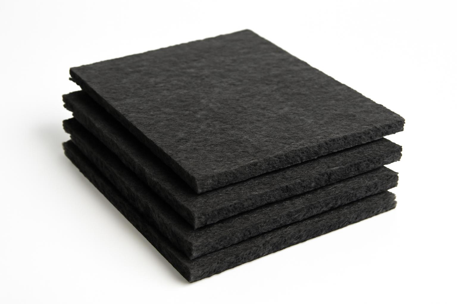
Carbon felt is generally a nonwoven mat made from carbonized fibers. Common precursor families include polyacrylonitrile, usually abbreviated PAN; rayon or viscose; and pitch. Before carbonization, the fibers are assembled into a web and consolidated through processes such as needle punching, felting, thermal bonding, or mechanical entanglement.
Carbonization converts the precursor into a predominantly carbon structure under a non-oxidizing atmosphere. The resulting felt is generally lightweight and porous, with grade-dependent compressibility and electrical conductivity. These broad characteristics do not define a single engineering material.
Two products labeled “carbon felt” can differ substantially in:
- precursor chemistry;
- carbonization and final heat-treatment history;
- density and basis weight;
- thickness and thickness tolerance;
- fiber diameter, length, and orientation;
- porosity and pore-size distribution;
- electrical and thermal transport;
- ash and individual impurities;
- flexibility, strength, and shedding behavior;
- coatings, purification, activation, or surface treatment;
- allowable atmosphere and service temperature.
The category name identifies a general construction, not a guaranteed specification.
| Term | Construction or treatment | Practical distinction |
|---|---|---|
| Carbon felt | Nonwoven precursor-fiber web that has been carbonized | Broad base category; properties remain grade-specific |
| Graphite felt | Carbonized felt given an additional, substantially higher-temperature graphitization treatment | More structurally ordered carbon; often considered when purity or electrical transport matters |
| Activated carbon felt | Carbon-fiber felt treated to develop extensive surface microporosity | Intended primarily for adsorption or specialized electrochemical functions |
| Soft felt | Flexible, compressible felt supplied as sheets, strips, or rolls | Conforms to curved or irregular surfaces but provides little structural support |
| Rigid felt or carbon–carbon insulation | Felt impregnated with binder, cured, and potentially carbonized or graphitized again | Dimensionally stable, machinable insulation or hot-zone component |
| Carbon cloth | Typically woven from continuous-fiber yarns | Regular in-plane yarn architecture rather than a lofted nonwoven web |
| Carbon paper | Thin nonwoven fiber mat, commonly wet-laid and resin-impregnated | Generally thinner and less lofted than felt |
Graphite felt should not be used as a synonym for every carbon felt. It starts with carbonized material but receives an additional graphitization treatment. Supplier-authored descriptions commonly associate this treatment with greater structural ordering, purity, and electrical conductivity, but the outcome depends on precursor, processing, density, and format. SHJ Carbon also distinguishes flexible felt from rigid material formed through binder impregnation and curing in its carbon-felt and graphite-felt comparison.
Activated carbon felt is another distinct product. Activation deliberately develops fine pores in or on the fibers, giving the material adsorption properties that ordinary untreated felt does not necessarily possess. Surface-area or contaminant-uptake values for activated felt must not be copied into a specification for conventional furnace insulation or untreated electrode felt.
Soft and rigid products solve different mechanical problems. Soft felt bends, wraps, compresses, and accommodates irregular geometry. Rigid felt, carbon–carbon board, and laminated insulation introduce binders, curing, additional heat treatment, or structural facings so that a component can retain its shape or be machined. Each finished construction needs its own documentation.
How carbon felt is manufactured
No single manufacturing recipe applies to every grade, but a typical route includes the following stages.
- Select and prepare the precursor. PAN, rayon or viscose, and pitch fibers have different processing behavior. Fiber length, diameter, sizing, and cleanliness can also influence the web.
- Form the fiber web. Fibers are distributed into a loose mat by an appropriate textile-forming process.
- Consolidate the web. Needle punching uses barbed needles to mechanically entangle fibers through the thickness. Felting, thermal bonding, and other consolidation methods may also be used.
- Stabilize the precursor where required. Some precursors undergo an oxidative or infusibilization stage so that they retain their fibrous form during later heating.
- Carbonize the web. Heating in a non-oxidizing atmosphere removes much of the non-carbon content and converts the precursor into carbon-rich fibers.
- Apply optional post-treatments. These may include graphitization, activation, purification, coating, rigidization, lamination, or machining.
One manufacturer describes raw-fiber selection, needle punching, pre-oxidation, carbonization, optional graphitization, and post-treatment. Its published production bands are 600–1500°C for carbonization and 2000–3000°C for graphitization, but these are supplier-described ranges rather than universal recipes for every precursor or producer of carbon felt.
Carbonization
Carbonization is thermal conversion, not merely drying.
Temperature, residence time, heating rate, tension, gas composition, and pressure can vary by producer and grade. A single carbonization temperature therefore does not define all carbon felt.
Manufacturing temperature must also be distinguished from allowable service temperature.
Graphitization
Graphitization is an optional treatment at a substantially higher temperature. It increases ordering in the carbon structure and may be associated with differences in:
- electrical resistivity;
- directional thermal conductivity;
- purity and ash;
- stiffness or brittleness;
- dimensional behavior;
- manufacturing cost.
The direction and magnitude of those differences should not be assumed from the word “graphitized.” They require grade-specific data. Lower electrical resistance may be desirable in an electrode, while a change in thermal transport may be undesirable in insulation. Higher purity can matter in contamination-sensitive processing but may not justify additional cost in another furnace.
Activation
Activation is a separate operation used to create a much larger accessible internal surface. The product remains a felt at the macroscopic scale, but its fibers acquire an adsorption-oriented pore network.
Activation should not be treated as a universal upgrade. The correct response is to request comparative data rather than assume the direction or size of any change.
Rigidization and facings
Flexible felt can be converted into a rigid component through binder or resin impregnation, shaping or lamination, and curing. Further carbonization or graphitization can convert binder-derived material into carbon, creating a carbon–carbon construction.
A pitch-based patent record, for example, describes precursor-web formation followed by infusibilization and carbonization. Its proposed insulation route adds binder impregnation, lamination, curing, carbonization, and graphitization as separate manufacturing stages. This documents one possible route; it does not prove that every rigid felt is made the same way or delivers the patent’s asserted performance.
Optional graphite-foil facings can produce a smoother, more closed surface. Carbon–carbon plates and other laminates can add structural support. Coatings and purification steps may be used when particular surface or contamination requirements apply.
Treat every modification as a new system-level specification. Do not assume that a faced, coated, purified, or rigidized product retains the permeability, conductivity, purity, thermal behavior, or handling characteristics of the underlying soft felt.
Structure and properties: felt versus cloth and paper
Carbon cloth is typically woven from continuous-fiber yarns. Knitted carbon textiles also exist, but they are a related construction rather than the main comparison here. Carbon felt and carbon paper are both nonwoven, although their structures and production routes differ.
Carbon paper is commonly produced as a relatively thin wet-laid mat and impregnated with thermosetting resin. Felt is generally thicker and obtains cohesion through entanglement, felting, or bonding.
Felt’s open, interconnected fiber network commonly provides:
- high void volume;
- relatively large inter-fiber pores;
- through-thickness fluid pathways;
- compressibility under clamping pressure;
- conformability around irregular surfaces;
- a three-dimensional conductive framework.
A supplier-hosted comparison describes carbon-felt porosity above 90%, primary pores as large as 100 micrometers, and a typical untreated modal pore diameter of approximately 30–40 micrometers. It also proposes a broad compressibility tendency of carbon paper below carbon cloth below carbon felt for the materials discussed on that page.
Those figures and that ranking are not universal measurements. Porosity, pore size, and compression response vary with precursor, fiber diameter, density, web formation, needling, surface treatment, thickness, and applied pressure. The proposed compressibility order is a useful expectation to investigate, not a substitute for pressure–thickness measurements on the candidate grades.
It is also important to distinguish two pore scales.
Inter-fiber voids are the relatively large spaces between fibers.
Surface micropores are much smaller pores developed in or on individual fibers through activation or etching.
A felt can therefore be porous at more than one scale. Reporting only total porosity or an average pore size can conceal this hierarchy.
The preferred architecture depends on the application:
- Furnace insulation emphasizes low-density heat-transfer paths, dimensional behavior, purity, and protected-atmosphere compatibility.
- Flow-through electrodes require a balance among electrical contact, permeability, wetting, pressure drop, and reaction area.
- Adsorbents require suitable surface chemistry and micropore distribution as well as acceptable bulk-flow resistance.
Furnace insulation and protected-atmosphere heat service
Carbon felt’s low-density fiber network contains substantial void space. In a properly designed hot zone, that structure can limit solid conduction and interrupt heat-transfer paths. Flexible felt can also wrap curved components, fill gaps, and accommodate complex furnace geometry.
Documented industrial contexts include vacuum and protected-atmosphere furnaces, silicon and silicon-carbide processing, sapphire production, semiconductor manufacturing, and metallurgical heat treatment. A Penn State industry-project summary specifically identifies carbon-fiber felt insulation in silicon-carbide wafer manufacture and explains why insulation uniformity matters to furnace temperature profiles and process consistency during high-temperature physical-vapor-deposition processing.
Atmosphere comes first
The first furnace-selection question is not “What temperature can the felt withstand?” It is:
At that temperature, in what atmosphere, at what pressure, for how long, and under what mechanical conditions?
Supplier ratings approaching 2800–3000°C generally apply only to named grades used in vacuum, inert gas, or another protected environment. They do not authorize extreme-temperature operation in air. CeraMaterials, for example, lists 3000°C for specified PAN carbon, PAN graphite, and rayon graphite felts in vacuum or inert atmosphere while separately stating an oxidizing-use limit of 400°C for the products on its page.
The approximately 400°C figure is not a universal safe threshold, ignition point, or service-life guarantee. Oxidation depends on grade, exposed area, oxygen concentration, temperature, gas flow, impurities, pressure, exposure time, and cycling. A furnace buyer should request product-specific oxidation or mass-loss data under representative conditions.
Compatibility also extends beyond oxygen. Moisture, reactive gases, deposits, cleaning cycles, and contact with process species may affect the felt or transport contaminants. Translate “inert atmosphere” on a datasheet into the actual gas composition, pressure, leak rate, and exposure sequence used by the process.
A practical stop condition is simple: reject an extreme-temperature claim for engineering comparison if the supplier does not identify the applicable atmosphere and pressure.
Thermal conductivity needs complete test conditions
A thermal-conductivity value is not sufficiently defined for comparison unless the supplier also identifies:
- test temperature or temperature range;
- atmosphere and pressure;
- specimen density and thickness;
- compression state;
- heat-flow direction;
- fiber orientation;
- facing or coating condition;
- test method and specimen geometry.
Felt and carbon–carbon insulation can be anisotropic. Heat flow parallel to preferentially aligned fibers may differ from through-thickness heat flow.
A peer-reviewed furnace-insulation study provides a useful bounded example. Its particular graphitized, resin-derived carbon–carbon composite had a density of 0.16 ± 0.02 g/cm³ and thermal conductivity of 0.38 W/(m·K) at 2000°C. The composite used a strongly anisotropic X-Y-Z network designed to leave relatively few fibers aligned with through-thickness heat flow in that specific material and test program.
Those findings cannot be transferred to ordinary flexible felt. The studied material was needle-punched, resin-molded, cured, and graphitized rather than being an untreated soft blanket. The result also does not establish that long-fiber products universally outperform short-fiber insulation.
Flexible felt or rigid board?
Choose flexible felt when conformability, wrapping, low mass, field fitting, or accommodation of irregular geometry is central. It can be layered or cut to shape, but it requires suitable support and may be vulnerable to compression, movement, edge damage, or shedding.
Choose rigid board or rigidized felt when insulation must retain dimensions, be machined, support adjacent components, or maintain repeatable spacing. Rigidization adds structural stability but creates a different material whose binder-derived phase, shrinkage, outgassing, conductivity, and purity require separate evaluation.
A furnace hot zone may combine both: rigid panels for geometry, soft felt for joints or compliant layers, and facings where a controlled surface is needed. Evaluate the installed assembly rather than assuming that every component behaves like bare felt.
Carbon felt as an electrochemical electrode
Carbon and graphite felts are marketed as electrode backings and three-dimensional reaction surfaces, including for vanadium redox flow batteries. Specialist retailers list carbon and graphite battery felts in multiple precursors and thicknesses for flow-battery and related electrode uses.
Market positioning does not prove that any conductive felt will perform well in a particular cell. Nominal conductivity is only one part of electrode behavior.
Minimum screening data
Before comparing candidates, require:
- precursor and treatment state;
- initial thickness and density;
- in-plane electrical resistance;
- through-plane electrical resistance;
- test pressure or compression for each value;
- chemical compatibility with the intended electrolyte;
- ash and relevant element-specific impurities.
A resistance number without direction, specimen geometry, and compression is not suitable for comparison.
Application-critical data
For candidates that pass initial screening, compare:
- contact resistance against the intended current collector;
- compressed thickness and compression–recovery behavior;
- permeability in the intended flow direction;
- pressure drop at representative flow rates;
- electrolyte wettability and uptake;
- inter-fiber and surface pore distributions;
- electrochemically relevant surface area;
- surface chemistry or treatment;
- mechanical stability and fiber loss.
Validation testing
Final selection should use cell-level performance and durability data under representative:
- electrolyte composition and concentration;
- operating temperature;
- current density;
- state-of-charge range;
- compression;
- flow rate and flow-field design;
- cleaning or pretreatment method;
- cycle count and defined failure criteria.
Compression is a coupled trade-off
It also changes thickness and can affect the apparent bulk resistance.
The supplied evidence does not establish a universal optimum. The correct compression depends on the felt, current collector, cell geometry, electrolyte, flow field, current density, and allowable pumping demand. Resistance and permeability should therefore be measured at the same compression intended for the assembled cell.
Untreated, graphitized, and activated electrodes are not interchangeable
Graphitized felt may have different electrical resistance, purity, surface chemistry, and wetting behavior.
Flow, mechanical stability, contamination, and durability must also be tested.
There is no defensible universal ranking of PAN, rayon, pitch, untreated, graphitized, or activated felt for every electrochemical system. Choose through matched testing under the intended operating conditions.
Activated carbon felt for adsorption and filtration
Activated carbon felt is carbon-fiber felt treated to create a high-surface-area pore network. Its adsorption function is associated mainly with fine pores developed at the fiber surface, not simply with the large visible spaces between fibers.
This creates a hierarchical structure:
- larger inter-fiber voids provide bulk-flow pathways;
- smaller pores in the fibers provide adsorption area;
- surface chemistry influences which molecules are retained;
- felt thickness and packing affect residence time and pressure drop.
As a commercial example, one Graphite Insulation product family lists grade-specific surface areas of 950–1500 m²/g, micropore diameters of 17–20 angstroms, and micropore volumes of 0.8–1.2 ml/g. The same page lists iodine, benzene, and methylene-blue uptake values for individual grades of its activated carbon felt.
These are vendor-listed product specifications, not universal activated-felt properties or proof of performance against every contaminant. Iodine or dye uptake may help characterize a material, but it does not replace testing with the actual solvent, vapor, dissolved compound, or contaminant mixture.
Minimum screening data
Require:
- activated status and activation method;
- basis weight, thickness, and density;
- full pore-size distribution;
- relevant surface chemistry information;
- pressure drop at a defined flow condition;
- compatibility with the process fluid and housing.
Application-critical data
For the target contaminant, request:
- equilibrium adsorption capacity;
- dynamic breakthrough curves;
- inlet concentration;
- temperature and humidity;
- flow rate and residence time;
- felt or bed thickness;
- competitive adsorption data for mixtures.
Surface area alone cannot select an adsorbent.
Regeneration and lifecycle validation
Where regeneration is intended, request:
- desorption or regeneration method;
- regeneration temperature and duration;
- capacity retained after a defined number of cycles;
- contaminant mass balance;
- physical degradation, dust release, or dimensional change;
- disposal requirements for spent or contaminated material.
The cited vendor identifies solvent recovery, air purification, water treatment, vapor control, and filtration as applications. It also says adsorption remains approximately unchanged after repeated regeneration, but the page provides no cycle count, test method, contaminant, operating conditions, or independent validation. Treat that statement as a claim to verify rather than demonstrated lifecycle performance.
Most importantly, never assign activated-felt adsorption properties to ordinary insulation or electrode felt. Untreated carbon felt may have high bulk porosity without possessing the developed microporous surface needed for substantial adsorption.
Carbon felt, graphite felt, and precursor choice
The choice between carbon and graphite felt is a choice between documented grades, not merely between two labels.
| Factor | Carbon felt | Graphite felt |
|---|---|---|
| Primary treatment | Carbonized | Carbonized and then graphitized at substantially higher temperature |
| Structural ordering | Less graphite-like ordering | Greater graphite-like ordering |
| Typical formats | Soft felt, rolls, sheets, and rigidized products | Soft felt, electrode felt, purified insulation, and rigidized products |
| Purity | Depends on precursor and post-treatment | Higher purity is commonly claimed but must be verified |
| Electrical transport | Conductive, with grade-specific resistance | Lower resistance is commonly claimed for some graphitized grades |
| Thermal transport | Directional and condition-dependent | May differ after graphitization; not automatically better for insulation |
| Flexibility | Often soft and compliant | Can remain flexible, although some grades may be more brittle |
| Cost | Often positioned as the lower-cost option | Additional processing may increase purchase cost |
| Common uses | Protected-atmosphere insulation, electrodes, and heat shields | High-purity hot zones, electrodes, and protected-atmosphere service |
Graphitization can be attractive when purity, electrical resistance, or high-temperature dimensional behavior is decisive. These are reasons to investigate a graphitized grade, not proof that every graphite felt is superior to every carbon felt.
For insulation, greater structural ordering may coincide with different thermal transport. A graphite felt should not automatically be called the better insulator. Compare conductivity at the actual temperature, pressure, density, orientation, and compression, together with shrinkage and any relevant surface condition.
Does PAN, rayon, viscose, or pitch matter?
Yes, but precursor name is only one variable.
PAN-based felt is commonly available in soft insulation and electrode formats. Vendors sometimes position it as easier to handle or less expensive.
Rayon or viscose felt is sometimes marketed for lower high-temperature thermal conductivity or greater purity. These recommendations require confirmation under the intended conditions.
Pitch-based felt appears in manufacturing descriptions and insulation patents, but the supplied evidence is insufficient to establish a broad performance ranking against PAN and rayon.
One commercial PAN-versus-rayon comparison recommends PAN for handling and price while recommending rayon above 1800°C based on a claimed thermal-conductivity advantage. Its tabulated conductivity figures, however, are reported at 1150°C rather than at the higher temperatures used to support that recommendation. Buyers should therefore request the underlying high-temperature measurements rather than relying on the precursor label alone.
A controlled comparison would need to hold density, thickness, fiber architecture, heat treatment, orientation, compression, atmosphere, and test method constant. Without that control, an apparent precursor effect may instead reflect manufacturing or specimen conditions.
Choose by verified grade data and application performance, not by precursor name alone.
Selection checklist, purchasing questions, and practical limitations
Begin with the system rather than the catalog. The lists below are due-diligence questions, not a claim that every property is governed by one universal test standard.
1. Define the application and environment
Record:
- insulation, electrode, adsorption, filtration, or another function;
- continuous operating temperature;
- peak temperature and duration;
- heat-up and cool-down rates;
- number and severity of thermal cycles;
- vacuum level or operating pressure;
- process-gas composition;
- oxygen, moisture, and reactive-gas exposure;
- contact materials and possible contaminants;
- mechanical loads, vibration, and compression.
For furnaces, atmosphere should precede maximum temperature. For electrodes, electrolyte chemistry and installed compression should precede nominal conductivity. For adsorbents, the target contaminant and breakthrough requirement should precede surface area.
2. Request minimum base-material data
For every application, obtain:
- precursor family;
- carbonized or graphitized status;
- final heat-treatment history;
- soft, rigid, laminated, or coated format;
- thickness and tolerance;
- density and tolerance;
- basis weight;
- dimensions and usable area;
- fiber orientation where relevant;
- flexibility or rigidity;
- nominal carbon content;
- ash;
- element-specific impurity profile;
- purification method;
- lot and manufacturing traceability.
“High purity” is not a complete specification. Total ash can conceal an unacceptable concentration of one critical element. Contamination-sensitive buyers should define limits for the individual impurities that matter to their process.
3. Identify the gating properties
For furnace insulation, the minimum gating data are atmosphere-specific temperature guidance, thermal conductivity under relevant conditions, shrinkage, purity, and structural format. Depending on the process, also request:
- heat-flow direction;
- specimen density, thickness, and compression;
- emissivity;
- outgassing data;
- oxidation or mass-loss behavior;
- thermal-cycling results;
- support and fastening constraints.
For electrodes, the minimum gating data are resistance under specified compression, compressed thickness, permeability, pressure drop, wettability, chemical compatibility, and representative cell results. Advanced characterization may include detailed pore distributions, surface chemistry, and failure analysis.
For adsorption, the minimum gating data are target-contaminant breakthrough performance, pressure drop, process humidity and temperature, and regeneration requirements. Surface area and general uptake indices are supporting characterization, not substitutes for contaminant-specific testing.
4. Address practical limitations
Commercial technical guidance warns that carbon and graphite felt can oxidize in hot air and that some products may shed brittle fibers or dust. It also notes that residual binders or impurities may contribute to outgassing in vacuum service depending on the grade and process.
Obtain the current safety data sheet for the exact product, including any binder, coating, or treatment. Handling controls should be based on that documentation and on a process-specific hazard assessment. Used activated felt may also contain captured substances that create hazards not represented by the original material documentation.
Cutting and installation methods should limit edge damage and uncontrolled debris. In contamination-sensitive systems, installation cleanliness may matter as much as nominal bulk purity.
Do not rely on unvalidated advice for stapling, sewing, gluing, or otherwise fastening felt. A material that functions at room temperature may soften, oxidize, volatilize, contaminate the chamber, concentrate stress, or fail during cycling. Review compatibility with the actual temperature, atmosphere, substrate, process chemistry, and contamination limits.
5. Make supplier data comparable
Ask each supplier or laboratory to identify:
- the test method or agreed procedure;
- specimen dimensions and orientation;
- atmosphere, pressure, and temperature;
- conditioning and compression;
- measurement uncertainty where available;
- property tolerances rather than typical values alone;
- lot-level certificates of analysis;
- traceability and change-control policy;
- acceptance criteria and retest procedure.
Where no agreed application-specific standard is available, define the procedure contractually with the supplier or test laboratory. A named method is useful only if its specimen configuration and conditions represent the intended comparison.
Do not compare a typical value from one vendor with a guaranteed minimum or maximum from another as though they were equivalent. A conductivity result measured at one temperature, density, or orientation cannot be ranked directly against a result obtained under different conditions.
6. Normalize commercial quotations
Compare cost by usable area or volume while holding constant:
- thickness and tolerance;
- density;
- precursor;
- carbonized versus graphitized state;
- purification;
- activation;
- coatings and facings;
- roll or sheet dimensions;
- minimum order quantity;
- cutting and machining charges;
- packaging and lead time;
- usable yield and expected scrap.
Commercial offerings include soft felt, rigid boards, cylinders, composite boards, and machined components rather than one interchangeable commodity format. Carbon Felt Inc., for example, lists soft felt, rigid thermal products, composite boards, and machining services as separate product categories. A displayed per-item price is therefore not a dependable cross-product measure of value.
Lifecycle evaluation may also include installation labor, energy loss, replacement frequency, contamination-related downtime, electrode pumping demand, adsorbent regeneration, and disposal. Treat these as project-specific cost categories rather than assuming that any one of them will dominate.
7. Follow a disciplined decision sequence
- Identify the primary application.
- Define atmosphere, pressure, and process chemistry.
- Set continuous and peak service conditions.
- Choose flexible or rigid format.
- Identify the few properties that can disqualify a candidate.
- Compare only condition-matched data.
- Review impurities, safety documentation, handling, and installation constraints.
- Obtain representative samples and lot documentation.
- Test the candidate in the actual assembly or a credible pilot.
- Establish acceptance criteria before production purchasing.
Reject or pause a candidate when:
- an extreme-temperature rating lacks atmosphere or pressure;
- conductivity lacks temperature, orientation, or specimen condition;
- electrode resistance lacks compression and direction;
- adsorption claims lack target-contaminant breakthrough data;
- “high purity” is unsupported by an impurity profile;
- the delivered product differs in treatment, density, facing, or format from the tested sample.
The correct carbon felt is the documented grade that works in the intended system—not the material with the largest temperature, conductivity, purity, or surface-area number.
Frequently asked questions
What is the difference between carbon felt and graphite felt?
Carbon felt is a nonwoven fiber mat that has been carbonized. Graphite felt begins as carbonized material and receives an additional, substantially higher-temperature graphitization treatment.
That treatment increases structural ordering and may be associated with different purity, electrical resistance, thermal transport, brittleness, and price. The outcome remains grade-specific, so graphite felt is not automatically a better insulator or better-value material.
What temperature can carbon felt withstand?
There is no universal maximum. The limit depends on grade, precursor, heat treatment, density, atmosphere, pressure, exposure time, mechanical requirements, and the supplier’s definition of failure.
Ratings near 2800–3000°C apply to specified commercial grades under vacuum, inert gas, or another protected environment—not generally in air. Some supplier guidance lists oxidizing-service values near 400°C, but these are product-specific recommendations rather than universal safe thresholds for all carbon felt. Manufacturing heat-treatment temperature is not the same as continuous service temperature.
Is activated carbon felt the same as ordinary carbon felt?
No. Activated carbon felt receives an additional treatment that develops a high-surface-area microporous network in its fibers. Ordinary felt can have high bulk porosity and large spaces between fibers without possessing adsorption-oriented microporosity.
Choose activated felt using contaminant-specific capacity, breakthrough, humidity, regeneration, pressure-drop, and cycle-life data. Do not assign its surface-area or uptake values to ordinary insulation or electrode grades.
Is carbon felt woven, and how does it differ from carbon cloth or paper?
Carbon felt is nonwoven. Its fibers are consolidated through entanglement, felting, bonding, or related processes rather than woven yarn intersections.
Carbon cloth is typically woven from continuous-fiber yarns. Carbon paper is also nonwoven but is generally thinner, commonly wet-laid, and often resin-impregnated. Felt is usually more open, lofted, and compressible, although actual properties must be confirmed for the grades being compared.
Which specifications matter when choosing carbon felt for a flow battery?
Start with through-plane and in-plane resistance, contact resistance, compressed thickness, permeability, pressure drop, wettability, pore distribution, surface treatment, chemical compatibility, purity, and mechanical stability.
Evaluate these properties at the intended compression and under the actual electrolyte, temperature, current density, and flow conditions. Compression may improve electrical contact while reducing pore volume and restricting flow, so conductivity alone cannot identify the best electrode. Require representative cell-level cycling and durability data before committing to a grade.